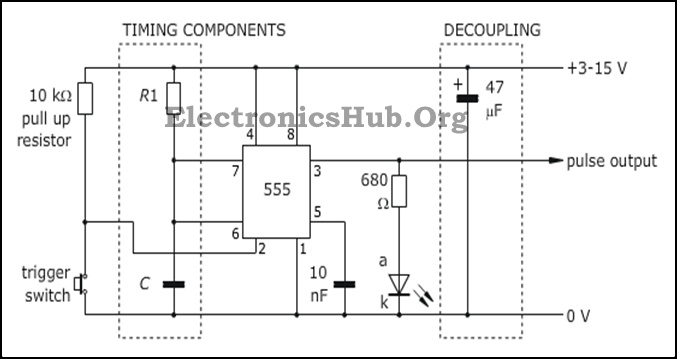
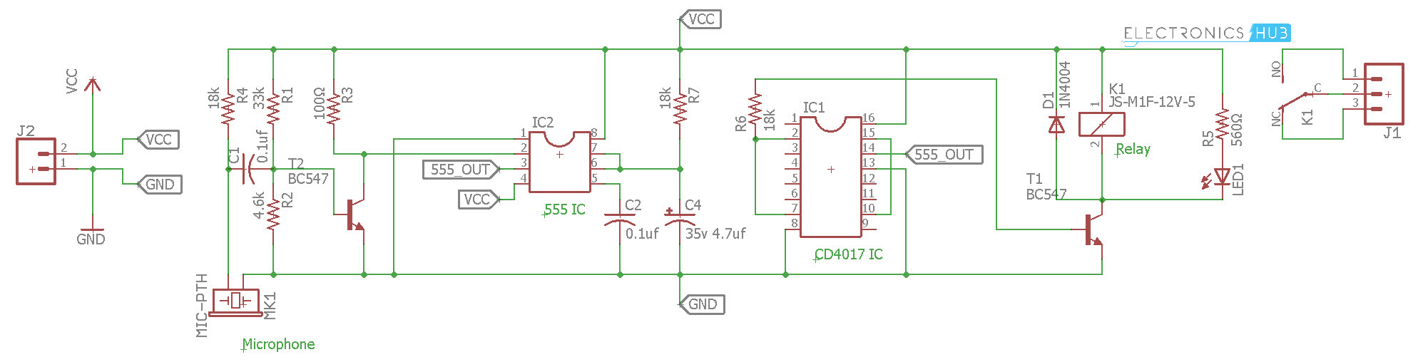
Clap On Clap Off Switch Circuit Diagram using 555 timer IC
$ 12.99
-
By A Mystery Man Writer
-
-
4.5(307)
Product Description
A "Clap On Clap Off" switch is an interesting phenomena that could be used in home automation. It works as a switch which makes devices On and Off by making a clap sound.
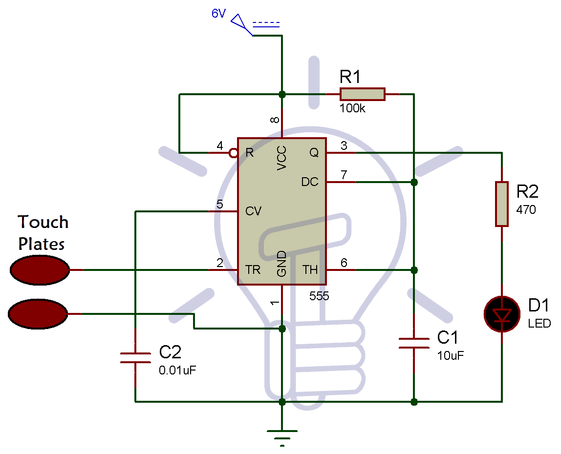
Simple Touch Sensitive Switch Circuit using 555 Timer & BC547 Transistor

Two Clap ON - Clap OFF Circuits - 555 IC

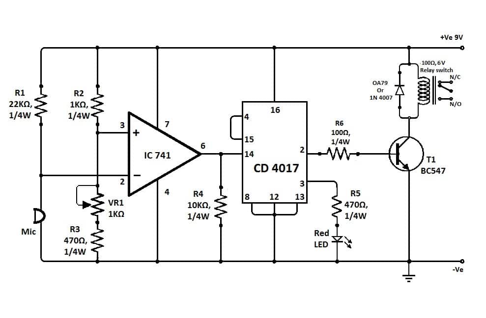
Clap Switch Using Op-amp and 555 Timer Ic : 6 Steps - Instructables
Clap switch circuit using IC 555
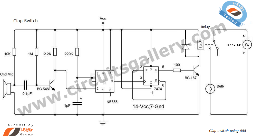
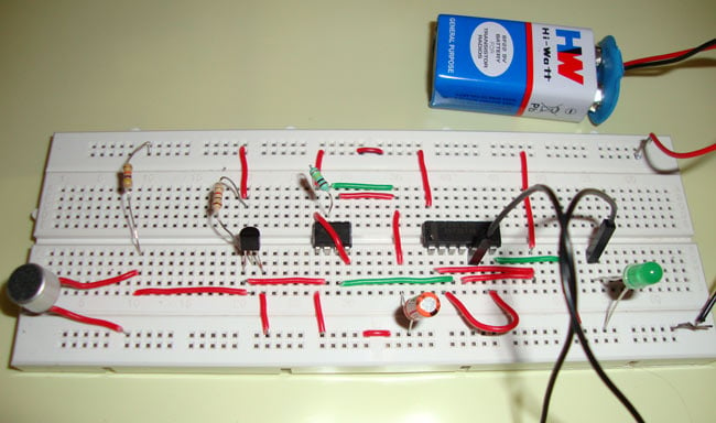
Clap Switch Circuit using NE555 timer IC under Repository-circuits -36847-
Clap Switch circuit diagram under Repository-circuits -36384-
Clap Switch Circuit for Devices Circuit Working and Applications
4 Simple Clap Switch Circuits [Tested]

Two Transient Clap Switch Circuits : 3 Steps - Instructables
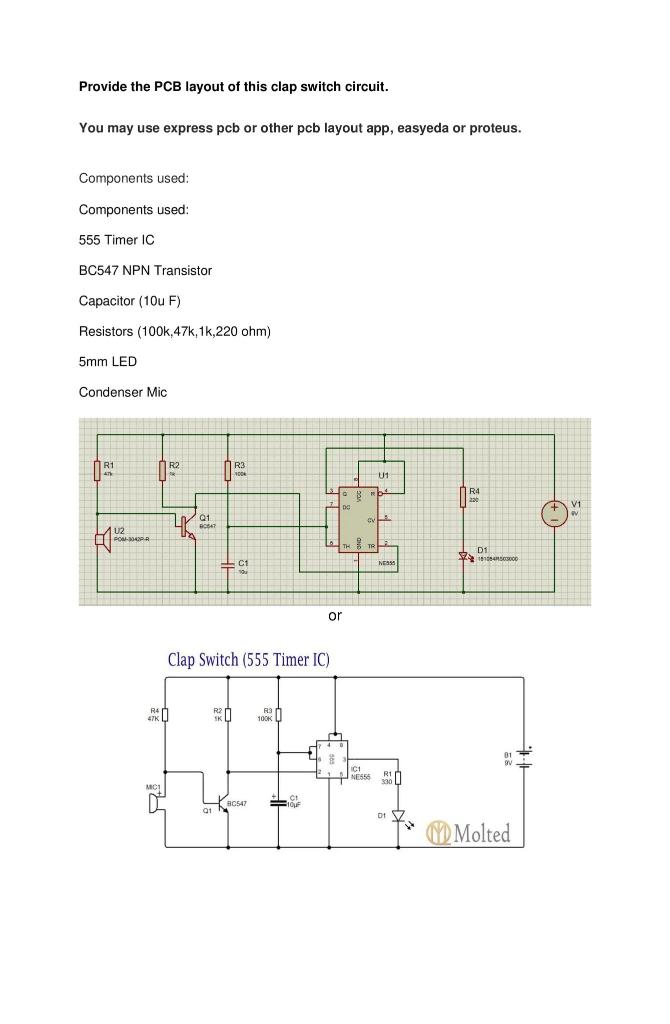
Solved Provide the PCB layout of this clap switch circuit.
Simple ON/OFF Switch (555 Timer IC)